SAO BSides Ballarat 2026
Firnsy from the Ballarat Hackerspace is developing a badge for BSides Ballarat 2026, and I thought it would be fun to add some SAOs for it. I have a few ideas, but I thought I’d start small and get something out the door, before committing to larger ideas.
SAO Basics
A SAO in this context is a “Simple Add-On”, a small PCB that can be added to an existing board to provide additional functionality. The “spec” is very simple - six pins in a 2x3 header, with VCC, GND, I2C SDA, I2C SCL, and two GPIO pins. The VCC is just 3.3V, the GND is ground, and the I2C pins are for communication with the main board. The two GPIO pins can be used for anything, but they are typically used for buttons or LEDs.
For more information, check out the SAO specification on hackaday.
The idea is keep it simple - its easy to do, and you can make it yourself on the day with a soldering iron and some basic components.
My first SAO
My first SAO is simple, just a LED connected to power. My first idea was simpler component wise, just a resistor and standard LED, but Firnsy suggested using a “smart” LED, specifically a WS2812B addressable RGB LED. This is slightly more complicated to setup, but actually makes the wiring easier.
Here’s the schematic I came up with:
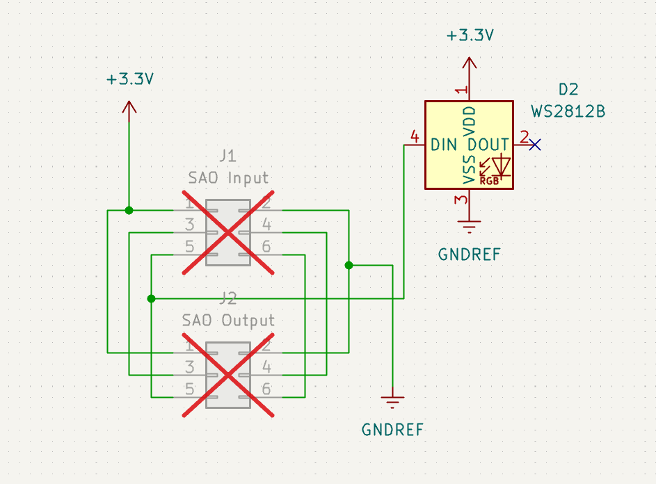
Note that most of the wiring is just for the pass-through, so you can chain SAOs if you wanted to. If you removed this, its just power (both VCC and GND) and the data line for the LED coming from pin 5.
This PCB can be reused for heaps of simpler SAOs, because 90% of the board is the design in this case. Here’s the design:
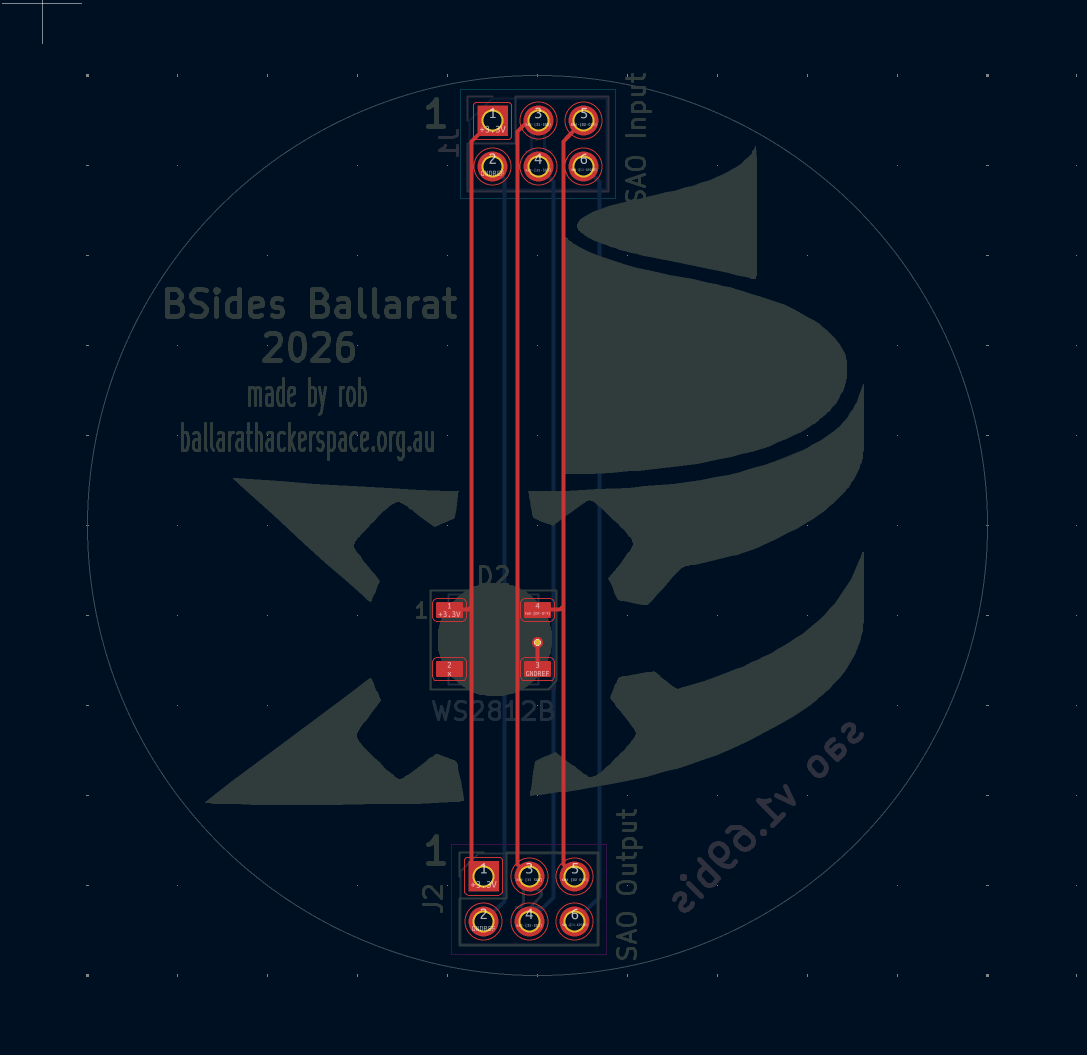
So it’s just the logo itself, and some text. I’ve “passed through” from top to bottom (I suppose it works the other way too), but those won’t be populated (at least, I’m not putting the components in) - it’ll be up to people to solder the header on themselves. The LED sits in the middle of the logo, and is a surface mount component, which I aim to solder myself. The hackerspace has a reflow oven, which will make this easier.
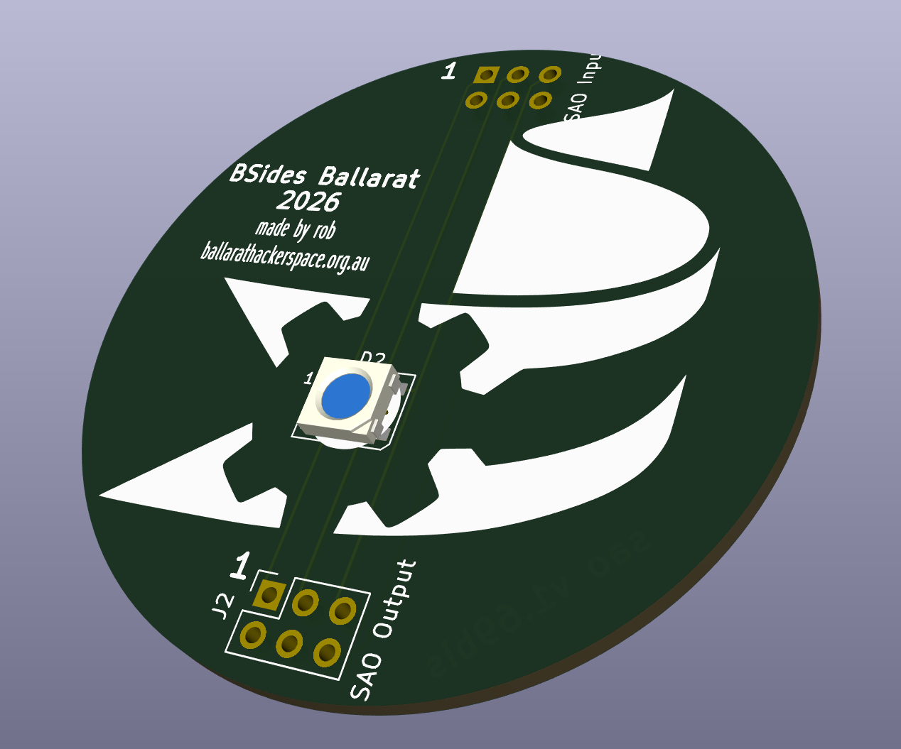
Finally, the end result as a 3D render:
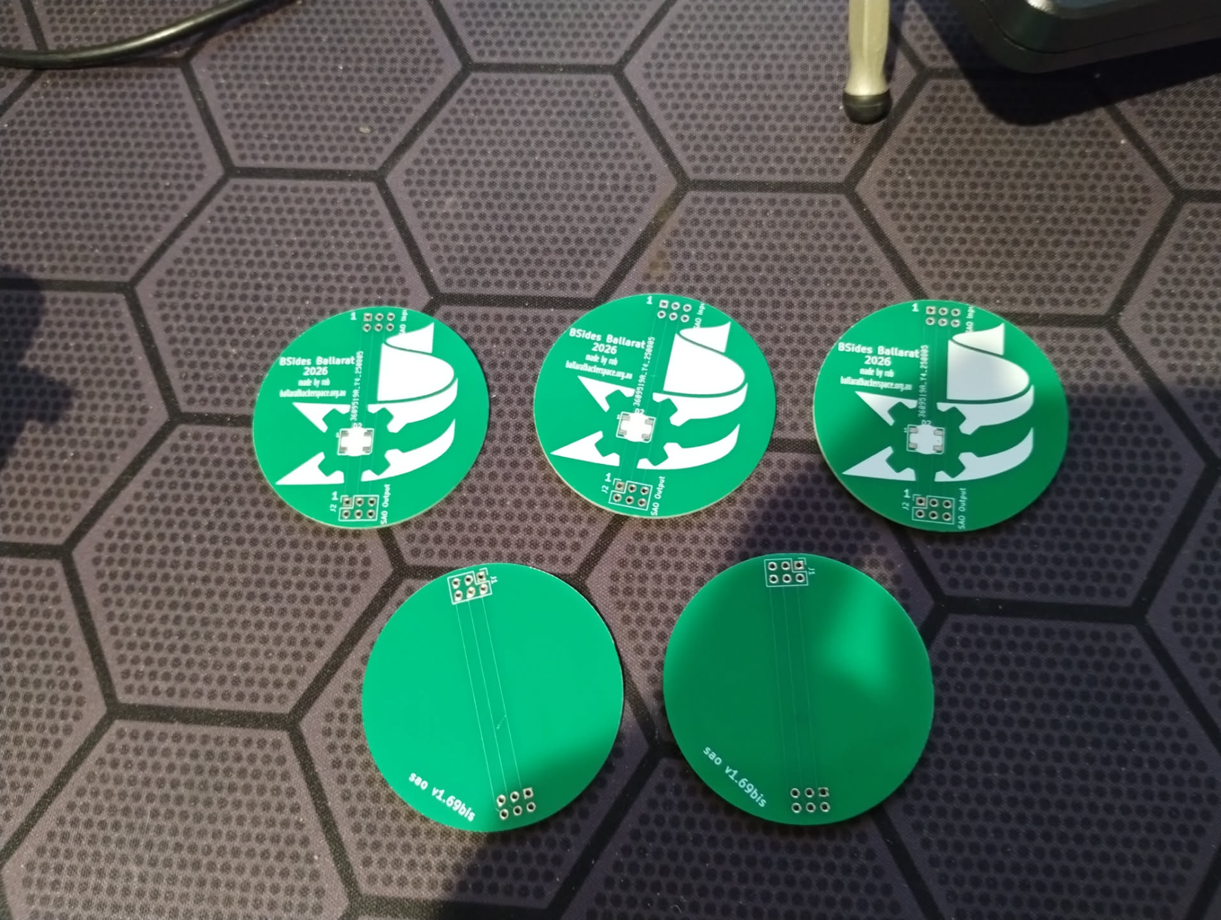
While the design is simple, this was only the second time I’ve designed a PCB, and the first time was quite a while ago. KiCad is super simple to use, except that you need the electronics background to understand what you’re doing. I asked Firnsy to check off the design, sent it to PCBWay, and they sent me back the boards about a week later.
Here they are:
and in action:
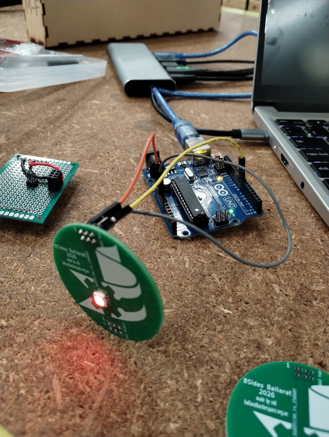
So overall a fun project - this board is done, so now I’ll order a full set, solder the LEDs on, and that’ll be project complete.
Next Steps
My next board is both a little more adventurous, and a little more complex. It is also much lower on the TODO list, so it may be a while before I get to it. My goals will be to include a microcontroller at least, so I get some experience with making boards with more complex components. Stay tuned!